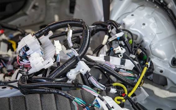
A cable harness that fails in service rarely fails because the wire gauge was wrong or the connector was under-rated. It fails because a bundle was routed across a sharp edge that cut through the insulation over six months of vibration, or because a clamping interval was too long and the harness flexed at a connector backshell until the conductors fractured, or because a sealing grommet was not seated correctly during installation and allowed moisture to track along the cable bundle into an enclosure. Routing and protection decisions made during harness design determine field reliability more consistently than component selection, and they deserve systematic engineering attention rather than being left to draughtsman convention or installer habit.
Route Planning Principles
Segregation of Circuit Classes
Power cables and signal cables should be routed in separate bundles with physical separation between them wherever the installation geometry allows. The minimum separation required depends on the voltage and current levels in the power bundle and the signal levels and noise sensitivity of the signal circuits. For defence and industrial vehicles, formal segregation rules are specified in standards such as DEF STAN 59-411 and ISO 14572, and these rules should be applied from the first layout rather than accommodated retrospectively. Retrospective segregation in a completed installation is expensive and often geometrically impossible.
Avoiding Sharp Bends and Edges
The minimum bend radius for a cable bundle is set by the stiffest cable in the bundle — typically the largest power cable — and must be maintained at every change of direction, including the exit from connector backshells and the entry into equipment enclosures. Industry standards typically specify a minimum bend radius of eight to ten times the cable outer diameter for fixed installations and twelve to fifteen times for flexing applications. Where the route geometry demands a tighter bend, a formed conduit or a purpose-made bracket that distributes the bend over a longer radius should be used rather than accepting a kink in the bundle.
Clamping and Support Intervals
Clamping supports the harness against its own weight and against vibration-induced movement. Too few clamps allow the harness to vibrate with amplitude sufficient to cause fretting at connector backshells and abrasion against adjacent structure. Too many clamps over-constrain the harness and create stress concentrations at each clamp, particularly in applications where thermal cycling causes differential expansion between the harness and the structure it is clamped to. As a general starting point, support intervals of 150 to 300 millimetres are typical for vibrating vehicle applications, with the specific interval determined by the natural frequency of the supported bundle span and the vibration spectrum of the installation.
The clamp itself must not damage the cable jacket. Metallic P-clamps with rubber liners are standard for most industrial and defence applications. The rubber liner grade must be compatible with the environmental temperature range and with any chemicals or fluids that may contact the clamp location. For applications with high levels of cable harness assembly complexity, routing and clamping studies using three-dimensional CAD models of the installation before hardware build significantly reduce the number of routing problems found during first article inspection and integration testing.
Abrasion Protection
Cable jacket materials vary widely in abrasion resistance, and the jacket that is correct for the electrical and environmental requirements of the circuit may not have adequate abrasion resistance for the route it must follow. Protective sleeving — braided glass fibre, expandable polyester braid or adhesive-backed PTFE tape — applied to sections of the harness that pass through bulkhead apertures, run adjacent to structure or cross moving components provides abrasion protection without changing the cable specification. The protective sleeve must extend beyond the zone of potential abrasion on both sides, and its ends must be secured to prevent it sliding along the bundle to expose the cables beneath.
Connector Backshell and Strain Relief
The highest stress concentration in a typical harness is at the connector backshell, where the relatively rigid connector body transitions to the flexible cable bundle. Vibration and cable weight cause the bundle to flex at this transition, and without effective strain relief, the conductors immediately behind the contact terminations accumulate fatigue damage that eventually causes fracture. A correctly specified backshell for the application grips the cable jacket — not the outer sleeve of the bundle — and prevents relative movement between the cable and the connector body under the vibration and cable-pull loads specified for the application.
For standard circular connectors including MS connectors, the manufacturer’s accessory range includes backshells with integrated strain relief clamps in a range of cable entry angles, and the correct backshell must be specified for the route geometry rather than defaulting to a straight backshell for all connections regardless of the cable exit direction.
Environmental Sealing of Penetrations
Where a harness passes through a bulkhead between zones of different environmental severity — from an outdoor weather zone to an indoor protected zone, or from a pressurised cabin to an unpressurised equipment bay — the penetration must be sealed to prevent the migration of moisture, dust and potentially hazardous gases from the more severe zone to the less severe one. Standard approaches include multi-cable grommet seals, potted bulkhead connectors and individual cable gland seals. The choice depends on the number and size of cables, the pressure differential across the bulkhead, and whether future cable additions or removals are anticipated.
Reputable harness and connector manufacturers in India with experience in defence and industrial applications can design and supply complete sealed harness assemblies including bulkhead penetrations, reducing the number of interfaces the integrating organisation must manage and providing a single point of accountability for the assembly’s environmental performance.
Conclusion
Cable harness routing and protection are engineering decisions with direct and measurable consequences for field reliability. Route segregation, bend radius compliance, correct clamping intervals, abrasion protection, backshell selection and bulkhead sealing each address a specific failure mode that is well documented in field failure data. Applying these principles systematically during harness design, and verifying compliance during first article inspection, eliminates the majority of harness-related field failures before they reach the customer.